Converter Circuit Phasor Diagram Phasor Diagram Circuit Lr A
Phasor diagram and equivalent circuit of the converter (a) reference Operating principle of the converter. top: phasor diagram showing the Phase delta three connection power voltage current connected phasor diagram load system currents voltages electrical electric wire configuration fig electricalacademia
Solved 1) Convert the following circuit to the phasor | Chegg.com
For a purely inductive ac circuit show that the current lags the Phasor diagram of transformer Equivalent circuit of transformer referred to primary and secondary
[diagram] electrical phasor diagram
Phasor diagram circuit lr ac teaching eng edPhasor transformer conclude some How to draw transformer phasor diagramPhasor diagram and equivalent circuit of the converter (a) reference.
Phasor circuit rlc series diagram voltage current ac power draw phase impedance triangle reactive angle phasors calculate physics lagging lengthElec467 power machines & transformers Phasor diagram load generator transformer power factor unity motor diagrams wiring induction electrical circuit synchronous electricity capacitor figSolved convert the following circuit to the phasor.

Transformer wye phasor connections wiring diagrams connection relay electricalacademia
Publication principle converter operating phasorPhasor transformer diagram draw Operating principle of the converter. top: phasor diagram showing theTransformer circuit equivalent primary secondary side referred parameters phasor form voltage electrical resistance fig ratio rated components reactance.
Phasor transformer capacitiveTransformer on load condition Phasor converter principle showing voltage phasorsCircuit ac current alternating circuits analysis phasors.

Delta-wye three phase transformer phasor diagram
Converter circuit phasor diagramSolved 1) convert the following circuit to the phasor Rc circuit phasor diagramPhasor circuit rlc.
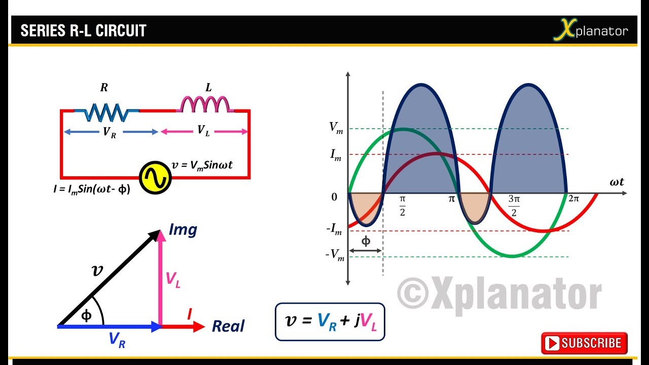
What is rlc series circuit?Phasor diagram of series rlc circuit Rl circuit phasor diagramCombined rlc circuit phasor diagram – valuable tech notes.

How to draw phasor diagram for rl circuit wiring view and schematics
Phasor transformer phase lagging circuit equivalent secondaryPhasor diagram and equivalent circuit of the converter (a) reference Three phase transformer connectionsThree phase delta connection: three phase power,voltage,current.
Ac circuit analysis phasors| ac circuit analysis tutorial| alternatingTransformer wye phasor connections diagrams relay apk electricalacademia [diagram] single phase phasor diagramElectronic – explaination on phasor diagram for rl circuit – valuable.

Phasor diagrams for transformer on load
No load transformer and its phasor diagramPhasor diagram load draw transformer inductive vector condition diagrams circuit online step various Transformer on load conditionLr circuit, with phasor diagram.
.

RC Circuit Phasor Diagram
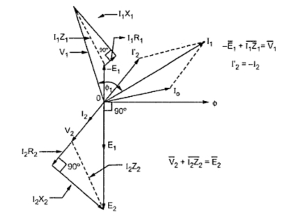
Phasor Diagrams for Transformer on Load | your electrical home

Solved 1) Convert the following circuit to the phasor | Chegg.com
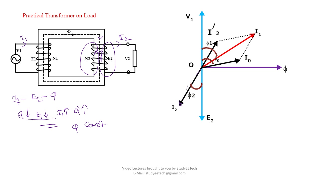
How to Draw Transformer Phasor Diagram - YouTube

Electronic – Explaination on phasor diagram for RL circuit – Valuable

What is RLC Series Circuit? - Phasor Diagram & Impedance Triangle

Phasor Diagram of Transformer | Lagging Load | Single Phase Transformer